Mo ZhouMechanical Engineering · University of Toronto
Projects/RC Aircraft Program/Jul 2026 – present
Airfoil Converter
An app that converts .csv coordinate files from airfoiltools.com into SolidWorks curve files, then lets you place, pitch and offset each airfoil and build whole wings from them, updating the curves in place inside SolidWorks.
Airfoiltools.com, a common tool for generating airfoils for CAD, gives each airfoil as a CSV of points. The file carries extra information that isn't always needed, and it isn't in a form SolidWorks' Curve Through XYZ Points import accepts.
Converting airfoils by hand was slow. Changing them afterwards (offsetting, editing the trailing edge, moving the section) often ran into rebuild errors in SolidWorks or meant a fresh export from airfoiltools.com, sometimes with the coordinates recalculated. Worst of all, placing one on any plane other than XY, YZ or XZ meant transforming every coordinate in the file by hand.
The converter started as the first step and has taken over the rest one problem at a time, so that most of the workflow and calculations happen in the app rather than in SolidWorks.
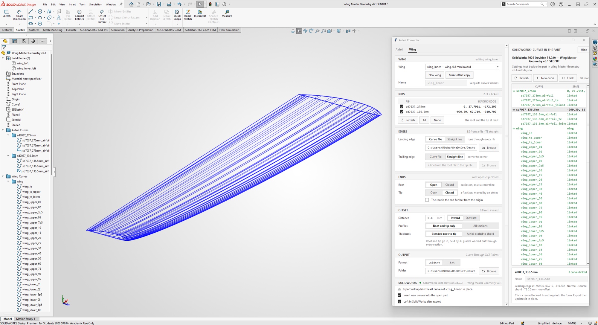
ImageThe Wing tab beside SolidWorks, building an inner wing offset 0.8 mm
CSV to Curve File
The first version read an airfoiltools.com CSV and wrote a SolidWorks Curve Through XYZ Points file (.sldcrv or .txt).
It also placed the airfoil while converting it. The CSV from airfoiltools.com usually puts the airfoil in the XY plane, which isn't always where it should be, as a wing often requires the airfoil to be on a specific plane, at a specific position and size. From the first day the app let you choose the plane (XY, YZ, XZ, or a plane through points you enter), set where the leading edge sits, which way the chord and the top of the airfoil face, and rescale it to a new chord. Angle of attack followed three days later.
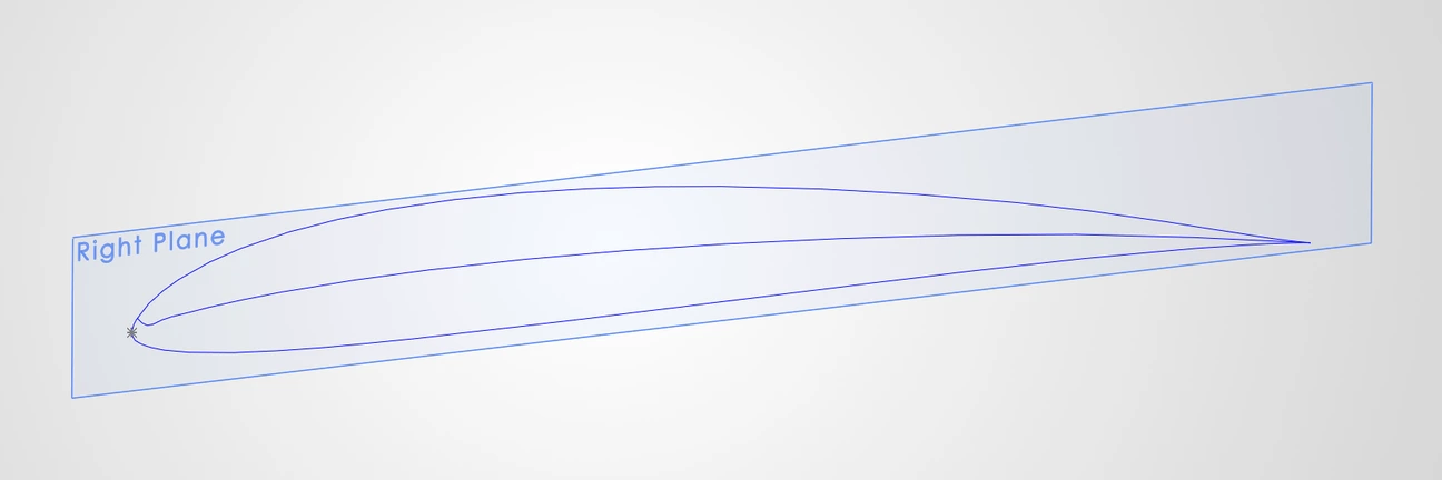
OutThe curve file, on the YZ plane: nose at the origin toward +Z, 2° angle of attack
ImageThe converted curve on the Right (YZ) plane, nose on the origin
Offset Curves
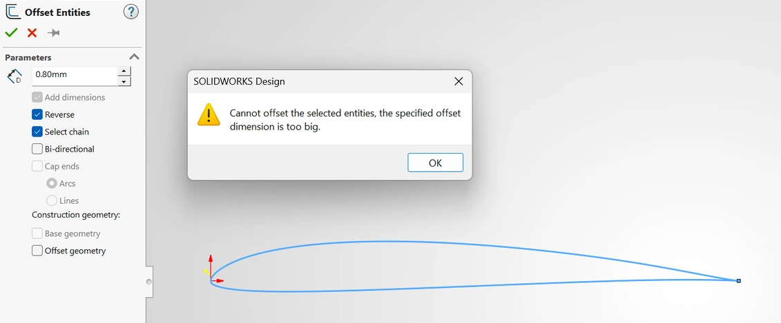
SolidWorks' Offset Entities usually ends in a rebuild error when it offsets an airfoil profile inward. However, an inward offset is often needed: to trim the wing's internal grid for spiral-vase printing (see [the internal-grid write-up] for more), or to build inserts between printed wing sections.
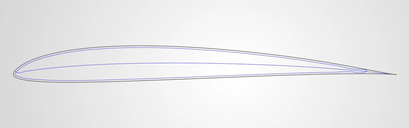
So the converter gained an offset of its own. It offsets the section itself and exports the result as a curve for SolidWorks to import.
BeforeSolidWorks refusing a 0.8 mm inward offset of the sectionAfterThe same 0.8 mm offset, made by the converter and imported as a curve
Printable Trailing Edge
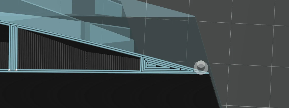
An airfoil exported from its profile usually ends at a sharp point, and the section is extremely thin around it. A printer nozzle can't lay down that point, so the slicer cuts it off on its own, and the printed part no longer matches the part in CAD.
ImageThe slicer’s preview: the model (translucent) runs to a sharp point, the extrusions stop short of it
So the converter gained a trailing-edge thickness setting. It cuts the section back to a vertical line where the airfoil is exactly as thick as the value you set, so the model in CAD already has the blunt edge the printer will actually make.
At first the chord simply ended at the cut, so the airfoil came out shorter than the one designed, and the final chord was hard to predict in CAD.
On 15 Aug the setting gained Keep chord after the cut, which scales the section back up about its leading edge so it retains its original chord while having the blunt edge.
SolidWorks Automation
This update drives SolidWorks directly. Through pywin32 and the SolidWorks COM API, pressing Export inserts the airfoil curves straight into the open part. A curve the app made can also be edited from the app afterwards: change its settings, export again, and the same features update in place, so a loft built on them rebuilds without a reference being re-picked. This cuts out most of the manual clicking and speeds the process up considerably, and it makes the airfoil curves in a design much easier to keep track of.
VideoExport inserting the SD7037 section and its camber line into the open part
Placing the V-tail of RC v2 showed how much was still worked out by hand: an airfoil on a plane that isn't aligned to any axis needed its plane points, leading edge and chord direction calculated and typed in. So the app learned to read them straight from SolidWorks.
Click a reference plane or flat face, then optionally a straight edge or sketch line for the chord and a sketch point or corner for the leading edge. While a pick is running, the app checks SolidWorks' selection five times a second through the COM API and treats each change as a click. It asks each selected object for its geometry: a plane or face gives its normal and a point on it, an edge or sketch line its two ends, a point its position. From these the app fills in the form: three points that define the plane, the leading-edge position, and which way the chord runs.
VideoPicking a plane, a chord line and a leading edge in SolidWorks, then exporting the airfoil onto them
Wing Tool
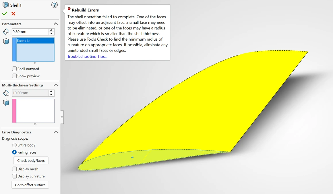
Working on the wing of RC v2 raised a harder problem. SolidWorks' Shell refused to shell the wing, failing with rebuild errors, and the app's own offset only works on flat airfoil profiles, which doesn't hold up along RC v2's curved leading edge. The wing needed a tool that could offset all of it at once.
ImageShell refusing the wing at 0.8 mm, its failing faces picked out
The Wing tab takes the exported ribs and the curves for the leading and trailing edges, and models the wing as close to SolidWorks' own loft as it can. SolidWorks doesn't publish how its loft builds a surface, so the model was matched against real lofts measured in SolidWorks.
On a wing with no taper or sweep, the offset wing could simply be built from the 2D offset airfoil at each section, which the earlier version of the tool already did by hand. On a tapered or swept wing, however, the outer skin is slanted relative to the ribs, so the same offset comes out thinner when measured to the outer skin. To correct for this, the app pushes each point of the offset further inward to compensate for how far the skin leans at that point. Past 20° of sweep, it measures the true 3D distance to the skin instead, adjusting until the offset is right. Where the wing is too thin for the full offset, such as near the trailing edge or around a tight nose, the offset is simply trimmed.
The offset wing goes into SolidWorks as root and tip profiles, edge curves and a set of surface guides that constrain the loft. A combine (subtract) or surface split between the two wings can then create the shell. Measured on the lofted solids SolidWorks built for the test wing below, a 998 mm wing offset by 0.8 mm, 92% of the inner skin is within 0.05 mm of the intended wall and 99% within 0.1 mm. What is left sits in two places: right at the nose, where the wall thins to 0.6 mm at worst, and on the upper surface between half and nine-tenths of the chord.
Interactive · the test wing’s sections, root to tip
InteractiveThe 0.8 mm wing as SolidWorks built it, cut every 25 mm from its STEP files. The wall is measured in 3D, inner skin to outer. Drag along the wing to move between sections.
The loft is driven from the app as well. Pressing Loft on the Wing tab, or ticking Loft in SolidWorks after export, selects the profiles and guides and builds the loft in the open part, for both the outer and the inner wing. The video below runs the current version from one end to the other, an airfoil CSV through to that lofted wing.
VideoThe current version end to end, from an airfoil CSV to the wing lofted in SolidWorks
Next
I will continue to work on wing offsets to improve accuracy. More will be added as new problems show up in future projects. What was learned here is also being carried into a new project currently in progress.